Updated 13 Jan 2013
Short description: I can control my 6 remote controlled wall sockets(lights) and the garage door from my android phone. I connected a arduino microcontroller to my internet connection and added 433 Mhz transmitting functionality. I created the arduino program and I created an android application to control the lights and garage door from my smart phone.
Hardware/cost
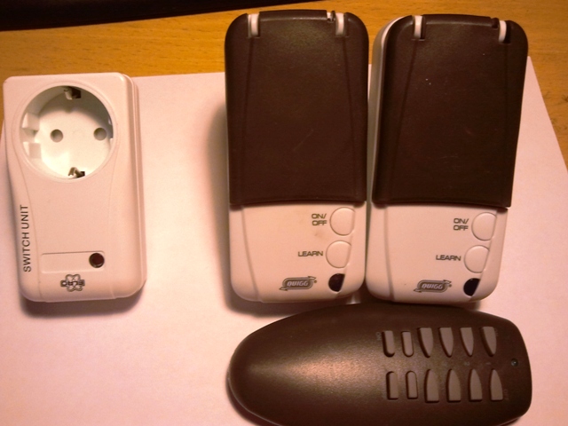
Below is a picture of my wall sockets. On the left is the ELRO. The ELRO has a DIP switch through which you can set the house code and device code. It has the PT2272 IC that detect coded signal. This is a fixed code. On the right are two QUIGG wall sockets and the remote control. The QUIGGs have a button to learn a certain code from the remote control.
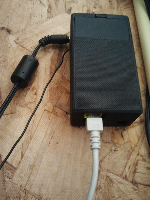
In below left picture is the enclosure mounted on the wall. On the left side it has a 12V wall wart power supply connector and a 17cm wire antenna, on bottom is the ethernet connector. In below middle picture I hold the the prototype board with the 433MHz transmitter, this board will be stacked onto the ethernet shield and the arduino. The transmitter is supplied with 12V and is powerful enough to transmit through two appartment building towards the garage door of my apartment complex, 5 floors below. It has one TTL input that is connected to a digital output of the Arduino. You need to toggle the output on and off according to a pattern that basically determined by the code of the receiving device. A stepdown converter (red PCB) on top the housing creates 5V for the arduino. In below right picture you see the prototype board stacked onto ethernetshield and arduino.


The arduino program is inspired by Rogier van den Berg. The program can learn the codes from the ELRO remote control (actually any remote control with the PT2262 IC) using a 433MHz receiver and transmit them and it has a small web application controlled from my android phone.
To control the garage door and the QUIGG wall sockets I had to learn the codes from the remote controls. I used a 433 MHz receiver and connected it to my sound card. I could determine the timings of the code and recreate the same signal in the arduino.
Below is a screenshot my first android app. It was created using MIT Appr Inventor. It uses HTTP POST method to send commands to my Arduino. In the Arduino the commands are processed and the lights are switched or garage door opened. The app also checks the connection by sending a HTTP GET request every 10s, when the GET request is asnwered with a HTTP OK then the buttons are enabled. In my router I had to forward one port to the Arduino, which has a fixed IP address in my network.
