Updated 29-march-2010
Short description: a single channel ECG amplifier was build and connected to the soundcard of my pc through a 1:1 audio transformer.
Desired signal: ECG: 0.05Hz-20 Hz 1mVpeak
Unwanted signal: 50Hz power line interference and others
Electrical safety
- Low power (battery operated 9V)
- input protection by means of diodes (voltage limiting) and serial resistors (limiting currents)
- 1:1 audio transformer (from an adsl splitter) for galvanic separation of the PC
SAFETY WARNING: DO NOT ACTUALLY CONNECT THIS CIRCUIT TO YOURSELF
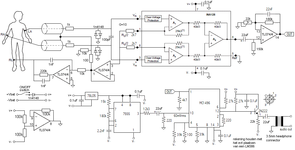
The ECG can be measured between left arm (LA) and right arm (RA). The electrodes a Ag/AgCl sticker electrodes, see figure below. The cables are fed to an instrumentation amplifier. The INA128 is well suited for ECG. It has a large gain for difference signals and a very small gain for common voltages on the inputs. This reduces a lot of disturbing 50 Hz power lines noise. The gain of the opamp is set by two resistors between pin 1 and 8. In this case the gain is set at 10.
Noise is further reduced by active guarding. The lead shields are actively driven to input potential. No charge can be build up between the core and shield of the lead. Thereby disturbance can hardly capacitively couple into the leads. This is implement by taking the average signal from the inputs, buffering this signal by a non-inverting opamp and then return the average input voltage to the guards of the leads. Since pin 1 and 8 are copies of input pins 2 and 3 resp., the average signal can be taken between the two resistors that set the gain.
An additional method to reduce noise is inverse common mode voltage feedback. Power line noise, like 50 Hz, is expected to disturb the inputs pretty equal, this is called common mode noise. This noise is substracted from the inputs by inverting the signal, using a inverting aopamp, and then feeding back it into a point relatively far from the RA and LA, like the right leg (RL). This is called Driven right Leg (DRL).
We have already reduced a lot of noise. Now we want to selectively zoom into the ECG. The output of the INA128 instrumentation amplifier is 1st order band pass filtered between 0.05-40 Hz using an inverting opamp that has a gain of 15x.
Finally we want to interface to a computer. These days, all computers have sound. We can use this low cost interface. However sound cards are based on audible sound (20-20000Hz), the low frequency ECG signal, which is lower than 20 Hz must be converted to a higher frequency. In the schematic is a local oscillator that produces a 2.4 kHz signal. This 2.4kHz signal is amplitude modulated with the low ECG signal, and fed in to the line input of the sound card. In the PC this mixed signal must be demodulated by software to obtain the original ECG.
Below is the schematic. To see the schematic in full size, open the picture in a new browser tab.

Below is the build ecg circuit.

Below is a figure of the amplitude modulated ECG recorded with a sound card
Bill of Materials:
- half shell box
- 3x 3M Red Dot 2249 Ag/AgCl ECG sticker electrodes (LA, RA and DRL)
- 4x mono jack audio connectors (LA, RA, DRLand to the PC)
- 9V battery, battery clip, power switch, power led and resistor
- 2x TL072, 1x INA128, 5x D1N4148, (tantal) capacitors, resistors)
- 7555 timer IC, MC1496 Modulator, transformer, 2N222 NPN transistor
- 78L05 voltage regulator
- 4x 8p DIP IC socket, 1x 14p DIP IC socket