Updated April 2014
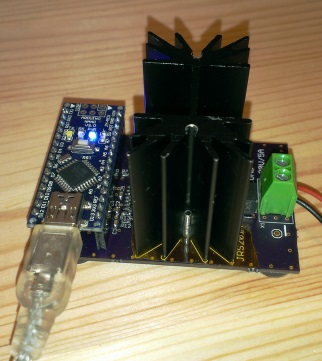
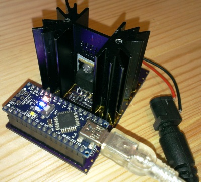
Summary: I designed an electric load. Using an Arduino Nano, the load can be programmed, and the voltage and current are measured. You can set a constant current (CC), a constant power (CP), or a constant resistance (CR) load by simply typing it in to the Arduino Serial Monitor. The circuit is designed for up to 30V, 5A, and 15W. An opamp, a mosfet, and a small sense resistor form the constant current circuit. The current is set using a DAC. Two other opamps measure the power supply voltage and the current. The circuit is powered from the Arduino USB voltage. I reflow soldered the board using the hacked toaster oven at the hackerdojo. Here are pictures of the reflow soldering process.
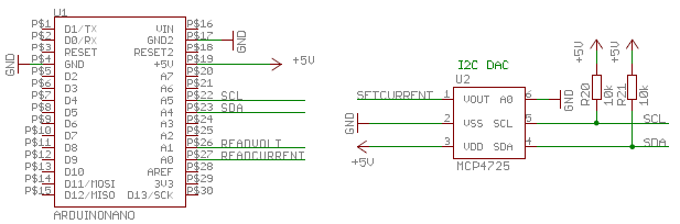
I chose to use an Arduino Nano board because it is small, cheap, easily interchangeable, it has a power supply that can be used to supply other circuits, and it can easily be programmed with the Arduino IDE. The Arduino is placed on female header connectors on the board. I chose to use the same DAC as on Adafruit and Sparkfun DAC breakout boards. The DAC can be supplied from 5V and the the output voltage is rail-to-rail. A description for using the MCP4725 DAC and library with Arduino can be found here on the Adafruit website. The DAC connects to the Arduino using I2C.
Opamp ICD1, mosfet Q1, and the 0.1 Ohm sense resistor form the constant current circuit. I chose the AD8608 opamp because it is a quad opamp, it can be supplied from 5V, and it has rail-to-rail voltage output. The mosfet functions as a voltage dependent resistance, and in the linear range. I chose a popular and widely available mosfet with a gate threshold voltage between 2.5 and 3V for currents up to 5A. I found the heat sink in a local electronics shop for $1. The mosfet, the heatsink, and their interface, have a combined thermal resistance of about 9 degrees Celsius per Watt. The maximum operation temperature of the mosfet is 175 degrees Celsius. This means that, at 25 degrees Celsius ambient temperature, maximal 15 Watt can be dissipated without active cooling.
To set a current of 1A, the DAC must output 1V. This voltage is divided by 10 using voltage divider R6 and R7 and this 0.1V is applied to the plus input of the opamp. The opamps adjusts it output voltage until it measures the same potential on it minus input, the feedback voltage from the sense resistor. That's the case when a current of 1A runs through the 0.1 Ohm sense resistor. The capacitor (C4) value in the RC filter may be changed to a suitable cut off frequency, or left out. R5 and C1 are designed to prevent the opamp from oscillating. C5 limits the AC gain (for high frequencies -> Lowpass), and R5 limits the DC gain.
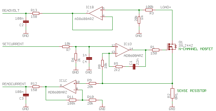
Opamp IC1B is used to measure the voltage of the power supply. R3 and R4 divide the supply (30V max) voltage by 6, so that it falls within 0-5V range of the 12 bit ADC of the Arduino. The opamp is simply used to buffer the voltage. The capacitor (C2) value in the RC filter may be changed to a suitable cut off frequency.
IC1C is used to measure the actual load current. The voltage over the sense resistor is amplified 10 times, by the opamp, and then connected to the 12 bit ADC pin of the Arduino. The capacitor (C3) value in the RC filter may be changed to a suitable cut off frequency.
Calibration need to be done because of tolerance in components and the USB supply voltage. Step 1: ADC readings depend on the Arduino USB supply voltage. Which is not always 5V. Here https://code.google.com/p/tinkerit/wiki/SecretVoltmeter I found code to measure the Arduino voltage rail. The Arduino power supply voltage is derived from an internal 1.1V reference and then back-calculated. In the "SecretVoltmeter"code I adjusted the 1126400L to 1106706L to match the back-calculated 5V to the actual measured voltage. Step 2: I multiplied load voltage ADC reading with a factor to match it with my multimeter. Step 3: I multiplied load current ADC reading with a factor to match it with my multimeter. Step 4: I multiplied DAC current setting with a factor to match it my multimeter. The accuracy of the voltage and current reading is limited mostly by the 10 bit AD converter. However the current is set with a accuracy of 1.2 mA/bit, which is sufficient to be able to test power supplies.
I ordered the 3 PCBs from OSHPark for just $25. The boards can be re-ordered here. A solder stencil was ordered from OSHstencils.
Schematic in Eagle and PDF. Layout in Eagle and PDF. Gerber file for PCB . BOM in XLS. Gerber file for Stencil.
There are definately improvements to be made. One is reverse voltage and over voltage protection of the opamps. Small signal diodes could be used to limit the opamp input voltage between 5V and GND. A second improvement is over load protection. The software should be capable of detecting when the voltage drops too much and reduce the current lineairly. A third improvement is changing the code to apply a pulsed load.
Using the Arduino Serial Monitor you can set the mode and value. For example you can type "cc100" to set a 100mA current, "cp1000" to set a 1000mW power, and "cr100" to set a 100 Ohm resistance. In overload condition, when the nominal power supply voltage drops, the CC circuit tries to maintain the current. This leads to an even further voltage drop and finally in a short circuit. In CP mode, the Arduino measures the voltage and adjusts the current so that the power remains constant. This is handy for testing power supplies designed to deliver a constant power. In CR mode, the Arduino measures the voltage and adjusts the current so that the resistance remains constant. This is handy if you want to simulate a resistor connected to the power supply. Especially if you don't have a box of power resistors of all kinds of values.
/*
Electric Load Modes:
- CC constant current load
- CP constant power load
- CR constant resistance load
Current output, voltage input, and current input calibrated
Voltage measurement 10bit 0-30V: 30mV/bit
Current measurement 10bit 0-5A : 5mA/bit
Power calculation : 60mW/bit
Current setting 12bit 0-5A: 1.2mA/bit
*/
#include <Wire.h>
#include <Adafruit_MCP4725.h>
Adafruit_MCP4725 dac;
int LedPin = 13;
int VoltPin = A1;
int CurrentPin = A0;
int VoltPinValue,CurrentPinValue,int_value;
float VoltPinVoltage,FltVoltPinValue,FltCurrentPinValue,LdVoltage,LdCurrent,LdPower,IntVolt;
long previousMillis = 0; //
int ledState = LOW; // ledState used to set the LED
long interval = 500; // interval to to flash LED
long ArduinoVccInmV; // Arduino Vcc voltage
float SetCurrCalFactor = 1.006;// calibration multiplication factor
static char line[30];
boolean haveLine, ret;
char c;
void setup() {
Serial.begin(9600); // setup serial
dac.begin(0x62); // DAC address with A0 connected to GND
pinMode(LedPin, OUTPUT); // Set LedPin as Output
int value=0; // from 0 to 4095 is from 0V to 5V
int storeflag=false; // store value in EEPROM (max 20,000 times)
dac.setVoltage(value, storeflag); // set the load to default value
Serial.println("Type 'cc100' to set 100mA, 'cp100' for 100mW, or 'cr100' for 100 Ohm");
}
long readVcc() { // from https://code.google.com/p/tinkerit/wiki/SecretVoltmeter
int result;
ADMUX=_BV(REFS0)|_BV(MUX3)|_BV(MUX2)|_BV(MUX1);// Read 1.1V reference against AVcc
delay(2); // Wait for Vref to settle
ADCSRA |= _BV(ADSC); // Start conversion
while (bit_is_set(ADCSRA,ADSC)); // measuring
result = ADCL;
result |= ADCH<<8;
//Original code below
//result = 1125300L/ result; // Calculate Vcc (in mV); 1125300 = 1.1*1023*1000
//Calibrated code below
result = 1106706L/ result; // Calculate Vcc (in mV); 1125300 = 1.1*1023*1000*(4940/5023)
return result; // Vcc in millivolts
}
void ReadVoltAndCurr(){
VoltPinValue = analogRead(VoltPin); // read value from voltage pin
CurrentPinValue = analogRead(CurrentPin); // read value from current pin
FltVoltPinValue= float(VoltPinValue); // convert VoltagePinValue to float
VoltPinVoltage = (FltVoltPinValue/1023.0)*IntVolt; // calculate voltage on voltage pin
LdVoltage = 6.030* VoltPinVoltage; // calculate load voltage, calibrated
Serial.print(LdVoltage); // print load voltage
Serial.print(" V, "); // print load voltage
FltCurrentPinValue= float(CurrentPinValue);// convert CurrentPinValue to float
LdCurrent = (FltCurrentPinValue/1023.0)*IntVolt*1.034;// calculate load current
Serial.print(LdCurrent); // print load current
Serial.print(" A, "); // print load current
LdPower = LdVoltage * LdCurrent; // calculate load power
Serial.print(LdPower); // print load power
Serial.print(" W"); // print load power
if(LdCurrent>5){ // warn if power is too high
Serial.print("Current to high!");
}
if(LdVoltage>30){ // warn if power is too high
Serial.print("Voltage to high!");
}
if(LdPower>15000){ // warn if power is too high
Serial.print("Power too high for heatsink!");
}
}
// CONSTANT CURRENT MODE
void CC(int DesiredmA){ // DesiredmA in mA
Serial.print("cc, ");
ReadVoltAndCurr();
Serial.println("");
float value=(DesiredmA/5000.0)*4095.0*SetCurrCalFactor; // calculate value to set the right current
int_value=int(value); // convert float to integer
dac.setVoltage(int_value, false); // value from 0 to 4095
}
//CONSTANT POWER MODE
void CP(int DesiredmW){
Serial.print("cp, ");
ReadVoltAndCurr();
float SetmA=DesiredmW/LdVoltage;
Serial.println("");
float value=(SetmA*4095*SetCurrCalFactor)/5000;
int_value=int(value);
dac.setVoltage(int_value, false); // value from 0 to 4095
}
//CONSTANT RESISTANCE MODE
void CR(int Resistance){
Serial.print("cr, ");
ReadVoltAndCurr();
float SetmA=LdVoltage/Resistance;
Serial.println("");
float value=(SetmA*4095*SetCurrCalFactor)/IntVolt;
int_value=int(value);
dac.setVoltage(int_value, false); // value from 0 to 4095
}
bool EditLine(char cin, char *cout, char line[], int size)
{
static int pos = 0;
*cout = cin;// echo by default
switch (cin) {// carriage return is ignored
case '\r':
break;
case '\n': // end-of-line
line[pos] = '\0';
pos = 0;
return true;
case 0x7F:
case 0x08:// backspace
if (pos > 0) {
pos--;
}
break;
default:
if (pos < (size - 1)) {// store char as long as there is space to do so
line[pos++] = cin;
}
else {
*cout = 0x07; // bell
}
break;
}
return false;
}
void loop() {
ArduinoVccInmV = readVcc(); // returns Arduino internal voltage in mV
IntVolt = ArduinoVccInmV/1000.0;// changes mV to Volt
unsigned long currentMillis = millis(); // flashes a LED
if(currentMillis - previousMillis > interval) {// as long as LED is flashing program runs
previousMillis = currentMillis;
ledState = !ledState;
digitalWrite(LedPin, ledState);
}
while (Serial.available() && !ret) {// read from serial until return
haveLine = EditLine(Serial.read(), &c, line, sizeof(line));
Serial.print(c);
}
if (haveLine) {
if (strncmp(line, "cc", 2) == 0) {
int value = atoi(line+2);
CC(value);
}
if (strncmp(line, "cr", 2) == 0) {
int value = atoi(line+2);
CR(value);
}
if (strncmp(line, "cp", 2) == 0) {
int value = atoi(line+2);
CP(value);
}
}// end of if (haveLine)
}//end of void loop()